Validating Roark’s Formulas for Stress and Strain - Fixed Rectangular Plate vs. ANSYS
Introduction
In structural analysis, classical plate theories provide quick and reliable estimates of stress and deflection in thin plates under various loading conditions. Roark’s Formulas for Stress and Strain is widely used for such calculations, offering analytical solutions based on well-established assumptions. However, with the increasing use of Finite Element Analysis (FEA), it is essential to validate these analytical results against numerical simulations to assess their accuracy.
A Thin plate is a flat structural element with a thickness much smaller than its other dimensions, typically less than 1/20th of its shortest span. Plates carry loads that act perpendicular to their surface and resist them through bending in two directions (x and y) and twisting forces.
This study aims to validate Roark’s formulas for a rectangular plate with all edges fixed under uniform pressure by comparing analytical results with FEA simulations in ANSYS. The goal is to evaluate the accuracy of Roark’s approach and understand its limitations when applied to real-world scenarios.
Assumptions for Analytical Calculations
The formulas from Roark’s handbook are derived under the following assumptions:
- The plate is flat, of uniform thickness, and made of homogeneous isotropic material.
- The thickness is not more than one-quarter of the smallest transverse dimension, and maximum deflection does not exceed half the thickness.
- All applied loads and reactions are normal to the plane of the plate (pure bending, no in-plane forces).
- The material remains within the elastic limit, ensuring that stress-strain behavior follows Hooke’s Law.
- For ease of discussion, the plate is assumed to be horizontal with the load acting downward.
With these assumptions, Roark’s formulas provide closed-form solutions for deflection and stress, which we will compare against FEA results obtained from ANSYS.
Problem Statement
We consider a plate (1000 mm × 1000 mm) with all edges fixed, subjected to a uniformly distributed pressure over its surface. The objective is to determine the maximum deflection and maximum stress using Roark’s analytical formulas and compare them with FEA results from ANSYS.
Given Data
Plate Dimensions:
- Length ($a$) = 1000 mm
- Width ($b$) = 1000 mm
- Thickness ($t$) = 10 mm
Material Properties:
- Young’s Modulus ($E$) = 200,000 MPa
- Poisson’s Ratio ($\nu$) = 0.3
Loading Condition:
- Uniform pressure ($q$) = 0.002 MPa
Boundary Condition:
- All edges fixed (clamped).
Governing Equations from Roark’s Formulas
For a plate with all edges fixed under uniform pressure, the formulas for maximum deflection and maximum bending stress are:
Maximum Deflection ($y_{max}$):
\[y_{max} = \frac{\alpha q b^4}{E t^3}\]Where $\alpha$ is a coefficient from Roark’s tables based on aspect ratio ($a/b=1$).
Maximum Bending Stress ($\sigma_{max}$ at center of long edge):
\[\sigma_{max} = \frac{\beta_1 q b^2}{t^2}\]Where $\beta_1$ is another coefficient from Roark’s tables based on aspect ratio ($a/b=1$).
Calculated Results
From Roark’s tables for a square plate with all edges fixed ($a/b=1$), we use:
- $\alpha = 0.0138$
- $\beta_1 = 0.308$
Substituting the given values:
Maximum Deflection: \(y_{max} = \frac{0.0138 \times 0.002 \times 1000^4}{200,000 \times 10^3} = \mathbf{0.138 \text{ mm}}\)
Maximum Stress: \(\sigma_{max} = \frac{0.308 \times 0.002 \times 1000^2}{10^2} = \mathbf{6.16 \text{ MPa}}\)
FEA Validation in ANSYS
To validate the analytical results obtained using Roark’s formulas, a finite element analysis (FEA) was performed in ANSYS. The objective of this simulation was to determine the maximum deflection and maximum stress under the same conditions and compare them with the theoretical predictions.
FEA Setup
- Mesh Details:
- Element Size: 7 mm
- No. of Elements: 40,898
- Boundary Conditions: All edges fixed (clamped).
- Loading Condition: Uniform pressure of 0.002 MPa applied over the entire surface.
- Material: Structural Steel (ANSYS General Material)
- $E$ = 200,000 MPa
- $\nu$ = 0.3
- $t$ = 10 mm
FEA Results
Deflection Result: 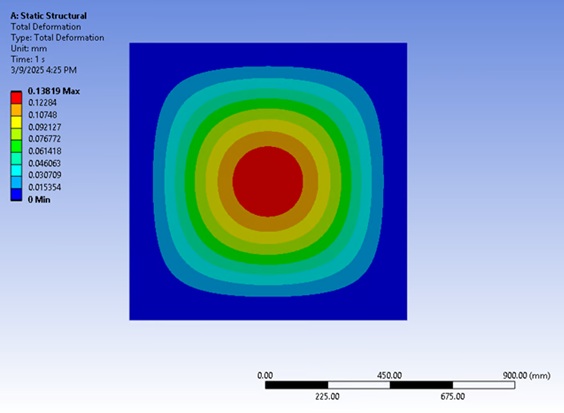 Figure 1: Maximum deflection contour plot.
Stress Result:  Figure 2: Von-Mises Stress contour plot.
Comparison of Analytical and FEA Results
| Parameter | Analytical (Roark) | FEA (ANSYS) | Difference |
|---|---|---|---|
| Max Deflection | 0.138 mm | 0.138 mm | 0.00% |
| Max Stress | 6.16 MPa | 5.511 MPa | 10.54% |
Conclusion:
- The maximum deflection from FEA matches exactly with the analytical result from Roark’s formulas, confirming the accuracy of the theoretical approach in predicting deflection for this case.
- The maximum stress from FEA is slightly lower (10.54% difference) compared to the analytical value. This is often due to mesh singularity at fixed boundaries or differences in how stress is averaged at the nodes versus the theoretical peak point.
- Overall, the analytical approach using Roark’s formulas provides a highly accurate estimate for deflection and a reasonably close prediction for stress.