Conservator for Transformers - Standards & Calculations
Sizing, Standards, and Practical Considerations
A conservator is a crucial component in oil-filled power transformers. It acts as a buffer tank that accommodates the expansion and contraction of transformer oil caused by temperature changes during operation. This ensures the internal pressure of the transformer remains stable and prevents oil overflow or vacuum formation.
What Do the Standards Say?
Different standards provide guidance on conservator sizing and design. Here’s a summary from three key sources:
1. IEC (International Electrotechnical Commission)
“The size of the conservator or expansion system shall be sufficient to accommodate the change in liquid volume from the coldest ambient when the transformer is de-energized to the highest mean liquid temperature experienced when the transformer is loaded to the highest level allowed.”
Key point: Must accommodate oil volume changes from cold start to full load temperature.
2. CBIP (Central Board of Irrigation and Power)
“Conservator should have a capacity between the highest and lowest visible levels equal to 7.5% of the total cold oil volume in the transformer.”
The capacity of a conservator tank shall be designed keeping in view the total quantity of oil and its contraction and expansion due to temperature variations.
3. CEA (Central Electricity Authority)
“The conservator tank shall have adequate capacity with clearly visible highest and lowest levels to accommodate oil expansion from the minimum ambient temperature to a top oil temperature of 100°C. It should also handle specified overloads without overflowing.”
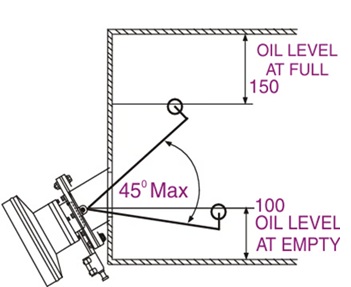
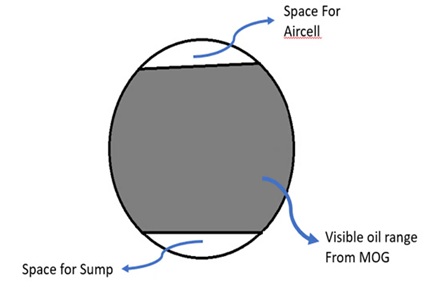
This visible range is marked on the Magnetic Oil Level Gauge (MOLG):
- Lowest visible level: 100 mm from bottom edge.
- Highest visible level: 150 mm from top.
So, at least 7.5% of the transformer’s oil volume should be visible between these points.
Practical Sizing Approach
While the standards define minimum requirements, many customers and manufacturers use a rule of thumb:
Conservator capacity ≈ 10% of total oil volume
This simplifies the selection process and provides additional safety margin.
Example: Sizing a Conservator
Let’s walk through a calculation example:
Details:
- Total oil volume ($V$): 62,000 litres
- Minimum ambient temperature ($T_{min}$): -5°C
- Maximum ambient temperature: 50°C
- Maximum Oil temperature rise: 45°C
Maximum oil temperature ($T_{max}$): \(50°C + 45°C = 95°C\)
Expansion Volume Calculation ($\Delta V$):
\[\Delta V = V \times \alpha \times (T_{max} - T_{min})\]Where:
- $\alpha = 0.000718$ (volumetric expansion coefficient for mineral oil)
- $V = 62,000$ litres
- $T_{max} = 95°C$
- $T_{min} = -5°C$
\(\Delta V = 62,000 \times 0.000718 \times (95 - (-5))\) \(\Delta V = 62,000 \times 0.000718 \times 100\) \(\Delta V = 4,451.6 \text{ litres}\)
So, the conservator should accommodate an oil volume change of ~4,451.6 litres.
Choosing the Right Aircell
Even if the conservator size is right, using non-standard aircell sizes may increase lead time and cost. Therefore:
- Always choose a standard STP size.
- Ensure the expansion volume is equal to or greater than the calculated value.
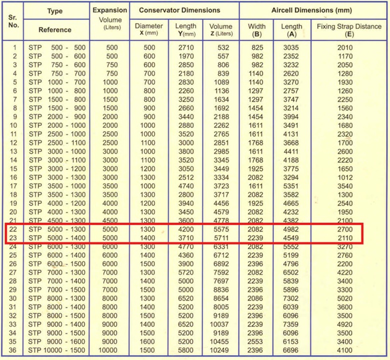
Figure 2: Standard Aircell Sizes (Source: Unirub).
Typical Selection Table:
| Option | Code | Diameter (mm) | Length (mm) | Expansion Volume |
|---|---|---|---|---|
| 1 | STP 5000-1300 | 1300 | 4200 | 5000 litres |
| 2 | STP 5000-1400 | 1400 | 3710 | 5000 litres |
Choose based on availability, space constraints, and preferred dimensions.
Conclusion
As per CBIP guidelines, a minimum of 7.5% of the total transformer oil volume should be visible between the highest and lowest levels in the conservator.
For our example: \(62,000 \times 0.075 = 4,650 \text{ litres}\)
The selected conservator, with an expansion capacity of around 5,000 litres, comfortably meets this requirement — thereby satisfying the CBIP visibility and capacity standards.